Please note, this is an information thread only.
I accept no liability for damage caused by the implementation of this cable design, incorrect termination and/or use of this cable design. It works for me and my HiFi friends and has done so for many years. If you are going to copy this design, you do so at your own risk. I can only suggest be careful with your terminations and double / triple check continuity to ensure you don't damage your HiFi computer equipment.
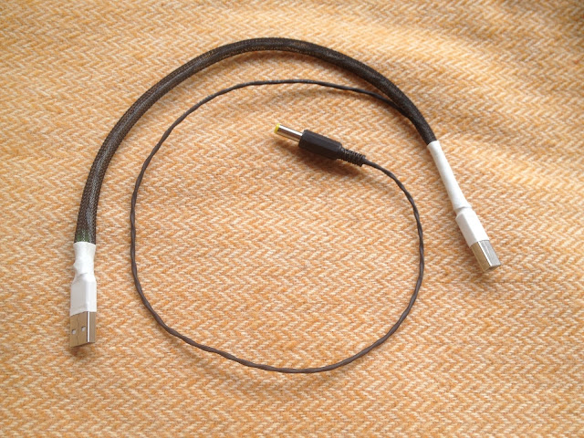
This blog in a few short steps will show an overview of how to make a linear powered DIY solid core USB lead.... We will be breaking out the power (5vdc +) and ground (gnd) connections, from the type B USB connector end to enable a linear power supply connection.
Why bother you may ask? Well if the quality of the 5vdc USB power source can be improved, we can yield quite noticeable improvements in USB sound quality and USB device rendering performance.

On implementation the most obvious benefit will be a subjective increase in detail and reduction in grain through the midrange and high frequency spectrum. Additional benefits in fidelity / transparency / overall spectrum detail / soundstage may also be noticeable, depending on the transparency capability of your audio system & ultimately your ear.
HOW?
We need to remove the dirty '5vdc feed' produced by your PC (on pins 1 & 4 of the type A USB end) and replace it with a more linear 5vdc supply from the source of your choosing. I personally use this power supply (Teradak linear power supply 0-9vdc adjustable... please note the unit now comes with a USB 5vdc output, making DIY super easy).
Not keen on starting a cable design from scratch? Too Difficult? Maybe try this simplified design........ CLICK THIS LINK.... The blogpost explains how to 'easily' modify a standard USB cable to accommodate linear power injection.
So lets get started.
STEP 1.... SELECT YOUR CONDUCTOR TYPE
My advice is try a few different types of core conductors and/or combinations to achieve a sound that suits your system.
STEP 2.... MAKE SURE YOU HAVE THE FOLLOWING
You are going to need the following items to make your DIY solid core, linear power USB lead.....
1 x Type A terminating USB connector
1 x Type B terminating USB connector
1 x LED (I used 2.1v rated LED)
1 x Resistor to suit your LED rating
1 x Some heat shrink / solder for terminations
1 x PVC / Teflon tubing / Heat shrink for Jacketing
1 x Soldering iron
Some signal wire
1 x DC plug.
1 x Your Time

Note: the Teralink power supply I used came with a basic copper DC power lead, which I de-soldered the connectors from. If you are making your own DC lead from scratch, the DC sizing is as follows, 5.5mm outside / 2.1mm inside.
If you are unsure on what resistor and LED values/combination to use... Simply use an LED calculator similar to this (LED resistor calculator). Personally I used a single 100ohm resistor, and the following LED from Radioparts rated at 2.1 forward voltage / Forward current 30mA.... I hope this helps.
http://www.radioparts.com.au/ProdView.aspx?popup=1&Category=SXLL44&Product=27940025&ProdDesc=LT521+GRE-LED+DIF-5MM+1.5MCD
Alternatively, I have read a single 1/2w 220ohm resistor (replacing the LED and single resistor) would do the same trick. Termination would be between 5vdc+ and Ground.
STEP 3.... SOLDER YOUR WIRE
This cable will require direct solder of signal cores between the type A and B USB connections, however as we will be powering the SPDIF device from linear power, connections 1 & 4 from the type B connection will be connected to a DC plug/or your alternate power source - not the USB type A connector (on the other end of the cable).
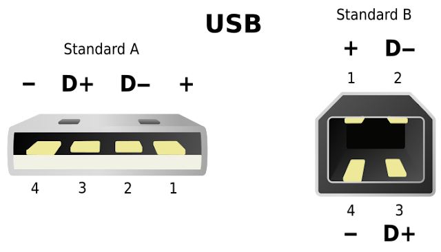
Click here for a wikipedia - usb type & pinout guide
To help you locate the correct USB pins for termination.
Pin 1 +5vdc
Pin 2 Data -
Pin 3 Data +
Pin 4 Ground
So this is what you should have;
Connector Type B (The square looking connector)
Spdif converter end
1 Power + which will connect the the centre of the dc connector
(solid CAT 5 core, the power cable used has little effect on the signal quality)
2 Data - > Connection to Type A pin 2 (solid silver in this build)
3 Data + > Connection to Type A pin 3 (solid silver in this build)
4 GND which will connect the the sleeve of the dc connector
(solid CAT 5 core, the power cable used has little effect on the signal quality)
5. Connector shell > terminate to Type A connector shell -
This termination may be required for some PC's. For instance my MATX PC worked fine without the connectors grounded, however my i5 laptop required both Type A and Type B USB connectors to be grounded for the USB signal to initiate.....
Note, CAT 5 cores were used for power.... These feeds don't require silver.
Copper does a fine job carry the low voltage 5vdc feed.\
Connector Type A (The flat looking connector)
Spdif converter end
1 Resistor leg (No polarity here, so choose a leg >Terminates to > LED + (anode)
2 Data - >Terminates to> Connection to Type A pin 2
3 Data + >Terminates to> Connection to Type A pin 3
4 LED leg - (cathode) Terminates directly to USB pin on connector
5. Connector shell > terminate to Type B connector shell
Refer to my comment above in red.
STILL UNSURE ABOUT WHICH PIN IS WHICH
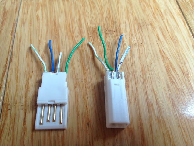
Just incase you are a little unsure about the pin placement on the usb connectors. I have cut up an old DIY usb lead (not this build), to help detail which pin is which on each of the type A and B connectors. I hope this clarifies.
To prevent any confusion, the type A and B connectors below are orientated as per the pin detail above.
In these pics, the key is:
Pin 1 +5vdc GREEN
Pin 2 Data - BLUE/WHITE
Pin 3 Data + BLUE
Pin 4 Ground GREEN/WHITE
Note: I have curled the blue/white conductor to help identify the core colours easier.
RESISTOR HELP
The resistor and LED are used to trick your computer into thinking it is powering the usb device (your spdif converter)...... Many computers will not allow data signal to pass until a power draw is measured and active.
If you are having trouble figuring out which end is the cathode and anode of your LED refer to the pic below. In short, the long LED leg is anode, and the shorter LED leg is the cathode (Flat side of the LED). Note, the resistor does not have polarity, so this is not important when terminating as above.
LED POLARITY
LED POLARITY
 You may notice my silver DIY cable design does not employ braided shielding, this will undoubtedly upset a few technophiles. Please note; I don't advocate for an absence of shielding in a USB design, and the ability to run a non shielded cable will be highly system dependent. These photos are for illustration purposes.
  Alternatively a copper twisted pair design (as below) retains the UTP twist offering decent EMI rejection. You will see an example of this below, I have foil wrapped the signal wires for added shielding.
 Either design subjectively provides improvements in sound quality when compared to traditional standard (non linear powered) USB cables. I would however suggest when DIYing a USB cable to keep it as short as possible, to reduce possible interference issues. My cables are typically no longer than 300mm, shorter is even better.
CHECKING TERMINATIONS
At this point, double and triple check your connection terminations are pin to pin!!....You don't wont to blow up any USB controllers, etc in your PC or audio device.
Do this with a multimeter. Pin to Pin testing, will ensure there are no incorrect terminations or shorts to the body of your Type A or B connectors. Remember to test Pin to connector shell - just to make sure.
Testing from Type B USB connector
Pin 1 - Should continuity test to power positive connector
Pin 2 - Should continuity test to USB Type A pin 2
Pin 3 - Should continuity test to USB Type A pin 3
Pin 4 - Should continuity test to power ground connector
Connector - Should continuity test between Type A and Type B connectors if implemented
Once your cable has been thoroughly tested with a multi-meter and you are satisfied with your terminations, plug the cable in.
WRAPPING UP

I believe this DIY linear USB cable mod provides a great alternative to pricier battery powered interfaces which although offer similar improvements in sound quality are significantly more expensive to purchase. In my opinion (and of some HiFi friends), a well made linear powered DIY USB cable (Cooper or Silver) will be one of the most significant investments in sound quality you can make for your usb spdif/aux device.
I am confident this DIY linear power cable design will be 'the USB cable' by which your future and current USB cable designs/purchases will be measured . So for now, until I find or build something better, my DIY solid core silver/copper linear powered USB lead will continue as my reference cable.
Can I suggest to any technophile doubters out there, who question this design to please try before commenting? you might be surprised, injecting clean linear power and using solid cores for signal transmission may have some validity?! ;)


This comment has been removed by a blog administrator.
ReplyDeleteWhat about the Ferrite on the end of one your cables. Is it recommended for silver cores or only used on utp design.
ReplyDeleteThis comment has been removed by the author.
ReplyDeleteWhere do you buy your silver usb connectors ?
ReplyDeleteDoes this led resistor trick always work? Some says ground should keep connected to source..
ReplyDeleteIs there any harmfull or Sound degreading possibility when ground not connected to source??
This comment has been removed by the author.
ReplyDeleteWell done Grizzly. Nice clear presentation.
ReplyDeleteMay I ask what sort of solder you used for the project?
I ask because I have melted some of the plastic on my USB connectors using a solder (96% Tin 4% Silver - Harris Stay Brite from Jaycar)with a 221 celcius melting point.
I have seen one poster on Computeraudiophile, GrahamJohnMiles, used Mundorf Silver Gold solder, which has a 217 Celcius melting point. In contrast, Michael, a professional from Elijah Audio seems to mostly use Cardas Quad Eutectic, which has a lower melting point of 185 celcius.
The other possible benefit of the Cardas might be that it is only 0.8 mm thick, while the others listed are 1 mm thick. I wondered if this might help with the narrow 0.8 mm wells used in USB connectors.
So this is why I asked what sort of solder you used or recommend for DIY USB cables.
Kind regards,
Ben
Thanks for the post. Found it super interesting. 2 questions:
ReplyDelete1) instead of ending the power with a DC, would there be any issue with ending it with another USB A with just the electrical terminals connected and no data? Would this essentially give you a cable like some of the newer 2 prong usb cables?
2) If I just wanted to transfer data and had a DAC that supported it, could I do away with the 5v and ground altogether?
Thanks,
Ryan
Hi All,
ReplyDeleteI just made my first USB for my DAC
i sounds great, but it only works for some short time, then the computer stops playing music, using jRiver om mac
kind regards
Vallemanden
This comment has been removed by the author.
ReplyDelete
ReplyDeleteHey good information, can you tell me where can i buy power cables online pls suggest me
Nice post on this topic. I like your blog very much because it has very helpful articles on various topics like different culture and the latest news.
ReplyDeleteWe provide high quality Email Marketing in Karachi that really gives response.
We appreciate you sharing this information about your project. You can easily contact us for Demolition Services In UAE
ReplyDeleteWe appreciate you sharing this information about your project. You can easily contact us for Guest Blogging On Thepixelmag
ReplyDeleteWe appreciate you sharing this information about your project. You can easily contact us for Sapphire Blue Color
ReplyDelete